XenServer® Enterprise Reference Architecture
Overview
This reference architecture defines a recommended approach for designing, deploying, and operating XenServer to support enterprise-scale workloads. It provides a validated foundation for hosting Citrix Virtual Apps and Desktops™ (CVAD) environments, as well as general server virtualization, with a focus on scalability, resilience, and operational simplicity.
The architecture is built around the concept of the XenServer resource pool as the core unit of scale and management. Each resource pool is designed to operate within a single data center (or a set of closely connected data centers) and supports predictable, high-performance workload execution. Deployments can be scaled horizontally by adding additional resource pools to meet growing capacity and organizational requirements.
Design Principles
The following principles summarize the design approach:
- Resource pool as the unit of scale: Deploy and manage workloads within well-defined resource pools, and scale horizontally by adding additional pools
- Workload isolation by design: Align resource pools to specific workload types to ensure consistent performance and operational behavior
- N+1 capacity model: Maintain sufficient capacity to tolerate a single host failure without impacting workload availability
- Separation of concerns: Clearly separate management, VM, and storage traffic to ensure performance, resilience, and security
- Explicit resilience strategy: Treat intra–data center resilience and inter–data center disaster recovery as distinct architectural concerns
- Operational simplicity: Introduce optional capabilities only where they provide clear value, avoiding unnecessary complexity
Together, these principles provide a consistent framework for designing XenServer environments that are scalable, resilient, and straightforward to operate, while remaining adaptable to evolving workload and organizational requirements.
This architecture assumes the use of remote block storage, integrated identity management through Active Directory, and secure management via TLS. Optional capabilities such as Workload Balancing (WLB), High Availability (HA), and Disaster Recovery (DR) can be incorporated based on workload requirements, but each introduces additional operational considerations that must be explicitly planned. The reference architecture is intended for enterprise environments requiring predictable performance and strong operational control. It is not optimized for specialized scenarios such as very large individual VM disks (>2 TB) or GPU-intensive workloads, which may require alternative designs or adaptations.
Overall, this document serves as both a design guide and an operational framework, enabling organizations to deploy XenServer in a consistent, supportable manner while retaining flexibility to extend and evolve the platform over time.
Assumptions and Scope
The architecture is based on a set of foundational assumptions about scale, infrastructure, and operational practices.
-
All hardware used must be listed in the XenServer Hardware Compatibility List (HCL)
- Each resource pool is expected to support up to 1,000 virtual machines, with overall deployments scaling by adding additional pools rather than expanding a single pool indefinitely, up to a maximum of 200 pools. All hosts within a pool are assumed to operate within a tightly coupled network boundary, ensuring consistent and reliable access to shared storage
- Hosts must have sufficient RAM to support the required workload and Control Domain with any performance caching requirements (see Sizing the Resource Pool), up to a maximum of 6 TB
- Hosts must either have local storage for XenServer OS (minimum 46 GB, ideally 70 GB), or ability to boot from SAN
-
Storage is assumed to be provided via remote block-based systems, with XenServer using LVM-based storage repositories. Efficiency and resilience are delivered primarily by the underlying storage platform, including capabilities such as thin provisioning to enable active allocation on use, and multipathing. Continuous and reliable storage connectivity is a critical requirement.
-
Networking follows a model of strict separation between management, virtual machine, and storage traffic. To achieve this hosts must be equipped with a minimum of either 2 NICs and 2 Fiber Channel connections, or 4 NICs. This separation is combined with bonded network interfaces to provide resilience and throughput, while avoiding configurations that introduce unnecessary dependencies or performance constraints.
-
Security and identity are treated as integral to the design. Management communications are secured using TLS, and integration with Active Directory is assumed for authentication and role-based access control. Administrative access is expected to follow standard enterprise security practices, with restricted use of local accounts and controlled exposure of management interfaces.
- Operationally, resource pools are designed around an N+1 capacity model, allowing workloads to continue running during host maintenance or in the event of a single host failure. Updates and upgrades are expected to be applied regularly to maintain supportability and security. Where disaster recovery is required, it is implemented as a coordinated operational process rather than a seamless or fully automated failover capability.
Optional capabilities can be incorporated where required, but are not assumed by default. These include:
- Workload Balancing (WLB)
- High Availability (HA) for workloads
- Disaster Recovery (DR) across data centers
Each of these introduces additional operational complexity and should be adopted based on clear workload and business requirements.
Out of Scope
This reference architecture is not designed for all scenarios and should not be treated as a universal solution. In particular, it does not directly address:
- Workloads requiring individual virtual disks greater than 2 TB
- GPU-accelerated or GPU-dependent workloads
- Architectures requiring seamless, active-active workload mobility across geographically dispersed data centers
In these cases, elements of this design may still be applicable, but additional architectural considerations and adaptations will be required.
Definitions
Terms and definitions to support the reading and understanding of this reference architecture.
| Term | Definition |
|---|---|
| Data Center | A collection of networked compute which is located closely together and have access to remote storage. All connectivity is expected to be low-latency, high-bandwidth, and highly reliable. In particular, XenServer hosts must not lose connectivity to storage. The compute can be configured to be resilient to failure within the data center and can form part of a disaster recovery solution for other data centers but is expected to operate as a standalone deployment during normal operation. This means there is no expectation of regular migration of workloads outside of the data center to form a wider resilience footprint. Network interconnect between any resources deployed within a data center is expected to have <2 ms latency and >=10 Gbps network throughput. |
| Close Proximity Data Centers | Multiple data centers with low-latency, high-bandwidth, and highly reliable, interconnect, expected to operate as if they are a single logical data center. Network interconnect between any resources deployed across these data centers is expected to have <5 ms latency and >=10 Gbps network throughput. |
| Geo Dispersed Data Centers | Data centers with large distances between them. Such data centers are expected to operate as independent entities, each with their own networks and storage. |
| Upgrade | A major product version change (for example upgrading from XenServer 8.4 to 9) |
| Update | Installation of packages within a specific single version of XenServer, providing additional features, bug fixes, and security fixes. |
| Resource Pool (Often shortened to Pool) | A management unit that groups together hosts and provides a single point to manage Storage and Networks across the set of hosts. For more detail see Resource Pools |
Architecture Blueprint
The expectations for resource pools are as follows:
- Each resource pool is designed for up to 1000 running VMs.
- Each resource pool is entirely located within a single data center or across close proximity data centers.
- Each resource pool provides for one specific use case, where all the workloads have similar characteristics for availability and performance. For small deployments, mixed use cases are possible but care must be taken when considering the load balancing and failure modes for the resource pools.
Examples of single use-cases are:
- Virtual desktops for a CVAD deployment
- Application Servers for CVAD deployment
- CVAD infrastructure
- General server virtualization workloads
Each resource pool will have the following attributes
- LVM protocol used for all remote block storage. It is not recommended to use GFS2 protocol.
- High availability for Pool Coordinator management
- Use of TLS 1.2 for all management communications
- Optional: Workload Balancing (WLB) for workload VMs
- Optional: High Availability (HA) of workload VMs
- Optional: Disaster Recovery (DR)
- Optional: XenServer Conversion Manager installed
Note:
The design can be scaled by creating multiple resource pools within data centers or across data centers to provide the workload where it is needed.
Construct each resource pool as defined in the sections below.
Core Resource Pool configuration
When building out a new resource pool the best practice is to configure a standalone host with network and storage configuration as required, then add other hosts to this pool. The additional hosts will gain the configuration as they are added to the resource pool.
Configure role-based access control
Connect all resource pools to a trusted Active Directory domain to allow AD users and groups to be easily managed and audited and to control access and permissions to the XenServer resource pools.
Note:
Do not use the default (root) account for management except in emergency conditions where it is not possible to authenticate via AD credentials (e.g. AD Domain Controller failure).
Provisioning Certificates for Hosts
All hosts in all resource pools should have a provisioned TLS certificate for use on the management network. For CVAD workloads the hosts will need to be resolvable by their FQDN in DNS.
All hosts must have a certificate provisioned to them; this may be a shared wildcard certificate or a per host certificate.
Note:
Some applications that use the XenServer APIs, such as some older versions of Citrix Apps and Desktops, require the use of an individual certificate for each host and don’t allow the use of wildcard certificates. See the relevant documentation for more details:
Any 3rd-party connections to the resource pool should use TLS and the FQDN to address the hosts in the resource pool.
Securing the communication to the resource pool
- Disable port 80
- Set SSH to Auto mode so that if the management toolstack fails, SSH is automatically enabled
Resource Pool Network Configuration
Separation is required for the following networks:
- Management network
- VM network
- Storage network (if using network based storage)
This separation can be provided by separate NICs or by using VLANs using the same NICs. If using Network based storage it is strongly recommended to use separate NICs for performance reasons.
Management and VM networks
The Management and VM networks should be operated on bonded NICs to provide resilience and throughput.
The bonds should be configured as LACP bonds where possible to ensure the best response to connectivity loss while maximizing the bandwidth availability. This will require the switches to be configured in a matching configuration. If the switches cannot be configured to support LACP then active-active is beneficial for VM networks. Management networks can use active-passive without any impact. For more information see Bonding Types.
Where possible, the switches should be cross-linked to the NICs to ensure that there is no single point of failure in the network transport and they should use separate power sources or redundant supplies, see Networking Best Practices for full details.
All the hosts in the pool must have fixed IP addresses on the management network; XenServer does not support the scenario where the host IP address issued by DHCP changes. If fixed DHCP addresses are used, the DHCP environment should be expected to be reliably available (e.g. as part of the network infrastructure) and should not be provided by a VM running on a host that depends on that DHCP server. Static addressing for infrastructure is recommended.
All host management networks need to allow connection to synchronized NTP servers to ensure their clocks stay aligned; this should be the same time source as used for the Active Directory providing the computer and user accounts for the role-based access control to ensure that clock drift does not occur and break the communication paths. This will also ensure that there are consistent timestamps for all system logs.
The full connectivity requirements that are required to enable operation of the environment are listed here.
Storage Networks
When using network-based storage the best practice is to use multipath support from the storage, which requires independent networks (i.e. different subnets). This typically means using single NICs rather than bonds and configuring appropriate subnets on each. Consult your storage provider for further recommendations.
Resource Pool Storage Configuration
Multipathing should be enabled. This must be set on all hosts individually, and there should be at least 2 paths available for all storage resources. These paths should be diverse across network/fiber channel infrastructure.
LVM is thick provisioned storage, so XenServer will require the full amount of storage needed for the VM disks created. This means that every disk and template will take the full capacity available even if only small portions of those disks are in use.
The recommendation is to use SANs that provide their own thin provisioning function to ensure efficient use of the storage. The SAN thin provisioning better utilizes the available storage by allocating disk storage space to VDIs as data is written to the virtual disk, rather than allocating the full virtual size of the VDI in advance. The amount of storage used should be monitored carefully by the administrator using tools provided by the SAN vendor.
If thin provisioning is used on the SAN, monitoring storage utilization is important; if the SAN capacity is exhausted such that further writes are not possible this can lead to VM failures and/or data corruption.
If using MCS to provision workloads for Citrix® environments it is recommended to use a small number of large LUNs for this as the golden image needs to be copied onto all LUNs which can be slow and make image provisioning take significant elapsed time, delaying the roll out of updated images.
Resilience Strategy
XenServer resource pools, along with their storage resources, are operated within a single data center (or within a collection of close proximity data centers).
These resource pools can be configured to be resilient to local server, storage, and network failures within the data center. In addition, resource pools can be used in combination to provide disaster recovery functions in case a data center fails and causes loss of an entire resource pool.
These are considered separately below.
Resilience within a Data Center
While workloads within a data center can be protected through a full DR configuration as described below, there are mechanisms for resilience within each resource pool to ensure high availability of the resources. These mechanisms are designed to be automated and used more frequently to protect against more common and localized issues. The following facilities are available:
- Management High Availability (through automated coordinator elections during unplanned outages)
- Workload compute High Availability (through automated VM restart on unplanned outages)
- Storage resilience (through storage multipathing)
- Network resilience (through network bonding and switch configurations)
To achieve this there is an expectation that the resource pool operates with a minimum of N+1 hosts, where N is the number of hosts required to operate the workload. This provides the capability to operate the resource pool at full capacity with one host unavailable.
Note:
N+1 Host capacity enables updating and upgrading resource pools without workload outage, allowing easy application of security updates and feature enhancements.
These facilities will provide a highly resilient deployment that is operated completely within a data center or across close proximity data centers. It will not support resilience across geographically dispersed data centers. The only way to support this is through the DR function described below (see Resilience across Data Centers).
Optional Capabilities
Workload Balancing (WLB)
- Use when: VM workloads have materially different and time-varying utilization patterns during their runtime and you want automated recommendations and/or rebalancing to maintain performance.
- Avoid when: Workloads are highly uniform (for example, many similar non-persistent VDI VMs) where initial placement and normal lifecycle operations already provide adequate balance, or where migrations are operationally undesirable.
- Operational impact: Adds an additional appliance to operate and monitor; includes a daily maintenance window during which WLB processing is unavailable.
WLB can be used to maintain the best host utilization and performance as workload usage changes over time.
Import the appliance into the resource pool and use the Management network for its connectivity. The Workload Balancing (WLB) appliance may be downloaded from the XenServer downloads page.
The default sizing for the appliance (2 GB Ram, 30 GB disk and 2 vCPUs) should be used.
Workload suitability
WLB should only be required when workload demand changes dynamically within VMs over their running lifetime. If WLB is used, every time a VM is stopped and started again it is placed optimally for the current workload immediately, so VMs should only need moving as host utilization changes. When the use case provides many similar VMs all carrying out similar tasks there is little value in using WLB and you can rely on the initial VM placement to provide workload balancing.
Adjust database maintenance window
The WLB appliance performs routine maintenance daily. By default, this is at 00:05 UTC. This should be configured to happen when there is low activity in the resource pool as there will be a WLB processing outage for up to 30 mins during this process. This does not affect normal operation, only placement optimization decisions; WLB will complete actions as soon as its maintenance is completed.
WLB parameter configuration
Many configuration settings can be left as defaults. This will set up the WLB feature to make recommendations to an administrator, and the administrator will have to apply these actions.
The default and expected configuration for this blueprint only requires the ‘Critical Thresholds’ and weightings to be adjusted to enable the resource pools to operate at maximum performance. These can be optimized through use, but some suggested start values are as follows:
-
CPU Utilization: The default for this is 90% critical threshold with a maximum weighting. This will ensure that once a host CPU reaches an average loading of 90% over the last 1.5 minutes, the WLB service will evaluate alternate locations for VMs to be run.
- If the performance of your VMs is being impacted at lower CPU utilizations, you can adjust this critical threshold with the aim of keeping the average CPU usage at a lower value across hosts where possible.
- Recommended initial critical threshold Value: 90%
- Recommended initial metric weighting value: Most important
-
Free Memory: There is no specific performance to be gained by keeping free memory on hosts, so migrating machines to keep memory free is an overhead that is not required.
- Recommended initial critical threshold Value: 0
- Recommended initial metric weighting value: Least important
-
Network Read and write: The default values for these are 25 MB/s. This means that if any host is utilizing more bandwidth for reads or writes it will be considered for re-location. This parameter is not relevant unless you have some VMs running heavy network workloads, and avoiding impact on other VMs is relevant.
- For many applications this is not a relevant factor, and the weighting should be set to the least important setting.
- For many modern networks this is a very low value and if this setting is relevant, we recommend setting this to allow good use of this bandwidth use before considering migration to another host.
- Recommended initial critical threshold Value: 90% of available bandwidth
- Recommended initial metric weighting value: Medium importance
-
Disk Read and write: The default values for this are 25 MB/s. This means that if any host is utilizing more bandwidth for reads or writes it will be considered for re-location. This parameter is not relevant unless you have some VMs running heavy disk workloads and avoiding impact on other VMs is relevant. If remote storage is used, then unless the bandwidth of the fabric is the bottleneck this is of no value as any impact on remote storage will impact all VM performance that uses that storage regardless of the host it is being operated on.
- For most modern storage and fabrics this is a low value and if this setting is relevant, it should be set to a higher value to allow for good use of bandwidth to be used. This should be set high enough that regular out of hours maintenance on VMs does not cause mass migration to occur when not needed.
- Recommended initial critical threshold Value: 90% of available bandwidth
- Recommended initial metric weighting value: Medium importance
High Availability (HA) for the Resource Pool
Full HA documentation is available here
There are 2 elements to consider for XenServer regarding High Availability
- Management HA: The ability to automatically maintain management operations when there is an unexpected outage of the coordinator host in the resource pool
- VM HA: The ability to maintain workload operations when there is an unexpected outage of a host in the resource pool
Both these aspects require specific storage and Network configurations. This is covered in the sections below.
One of the Storage LUNs available will be selected as the XenServer Heartbeat SR (see Heartbeats for Availability for full explanation of this requirement). If there is more than one LUN available, it does not matter which one is selected. A small amount (<5 GB) of space will be allocated from this LUN to provide the HA function.
This reference architecture is designed to support the maintenance of workload within the limits of the unexpected loss of a single host. The ‘Failures to Tolerate’ setting should be set to 1.
Note:
It is important to be aware of the following characteristics when using HA
- The resource pool must have at least 3 hosts
- Fencing refers to the mechanism that forcibly isolates a host that is considered failed or unsafe, ensuring it cannot access shared resources (especially shared storage) before virtual machines are restarted elsewhere. The larger the resource pool the greater the impact of host fencing is and the more likely it is to occur because of the communication path requirements. Careful consideration should be given in this respect to pools >16 hosts.
- HA should be disabled during host / resource pool maintenance operations to reduce the risk of unexpected outages while these maintenance activities are being undertaken.
- When using HA, care must be taken to ensure that the storage connectivity to the HA statefile SR and the networking is not disrupted. Disruption to these connections can cause hosts to fence unexpectedly to protect the operations of the resource pool. This means that careful consideration must be taken when undertaking maintenance on the infrastructure to ensure connectivity is not lost.
Alternative approaches for Management HA
If you are using HA to provide reliable, highly available management connectivity, then the following approaches should also be considered to avoid the limitations listed above.
Implement host monitoring
Integrate XenServer hosts with a 3rd-party monitoring solution to detect when a host is unresponsive.
Manually recover management connectivity
If the host that is uncontactable is the coordinator and management operations are unavailable, then all the other hosts in the resource pool will enter emergency mode and allow remote connectivity to be established to them to elect one of them as a new pool coordinator. This can be performed using the remote language bindings. Examples below are given for xe CLI and PowerShell.
xe CLI:
xe -s <server_IP> -u <username> -pw <password> host-is-in-emergency-mode                     -> Confirm election possibility
xe -s <server_IP> -u <username> -pw <password> pool-emergency-transition-to-master           -> Designate current host as new master
xe -s <server_IP> -u <username> -pw <password> pool-recover-slaves                           -> Reconfigure member servers to new coordinator

<!--NeedCopy-->
PowerShell:
Invoke-XenPool -XenAction EmergencyTransitionToMaster          -> Designate current host as new master
Invoke-XenPool -XenAction RecoverSlaves                        -> Reconfigure member servers to new coordinator

<!--NeedCopy-->
VM HA
Workload Balancing (WLB) VM
This VM should have the restart priority set to restart to ensure that any WLB functions are not lost after an unexpected outage. It should be in the first start group 0.
Other VMs
Depending on the exact usage of XenServer, additional VMs might be configured to use VM HA. The following are suggestions for some use cases.
Decision guidance (VM HA): Use VM HA for workloads where automated restart after an unexpected host outage materially improves service continuity, and where the pool is sized N+1 to absorb the outage. Avoid VM HA for workloads where external brokering/orchestration already provides restart or scale-out behavior (for example, many non-persistent CVAD workloads), or where restart order and dependencies are difficult to control.
Note:
VMs added to the resource pool after HA is configured will default to ‘Do Not Restart’. The HA will need to be reconfigured after VMs are added to the environment if required.
-
PVS and non-persistent MCS VMs: Do not configure these VMs with any HA. Make sure these are set to
Do Not Restart. Other VMs should be available to provide immediate services for end users and Citrix Virtual Apps and Desktops will provide power management functions to support the restarting of these VMs either when an end user requires it or through auto scale functions to support the expected demand see AutoScale. This will provide a more optimized outcome for the combined Citrix environment. -
MCS Persistent VMs: These should be set to ‘Restart’. The configuration being designed should ensure there is enough RAM and CPU available to operate all the VMs in the pool when there is 1 host out of service (for update or maintenance or outage) so this configuration will be possible.
-
General Server Virtualization workloads (any workload not being used to run Citrix VDAs): These should be set to ‘Restart’. The configuration being designed should ensure there is enough RAM and CPU available to operate all the VMs in the pool when there is 1 host out of service (for update or maintenance or outage) so this configuration will be possible. The VMs can be configured to use the start groups and delays as required to ensure the workload restarts as required. This could be used to prioritize workloads that other services depend on such as Active Directory, DHCP and DNS service providers.
Resilience across data centers
Optional:
Disaster Recovery (DR) across data centers. This reference architecture can support DR if necessary, with additional design and operational considerations.
Decision guidance for DR
- Use when: You have a defined business requirement for site resilience, a replication-capable storage platform, and agreed recovery procedures (RPO/RTO) that require VM recovery at a secondary site.
- Avoid when: You need frequent workload mobility between sites, or you do not have the operational capacity to test and execute failover/failback processes. For CVAD, do not assume that hypervisor connectivity and certificates will seamlessly fail over without a coordinated CVAD DR design.
- Operational impact: DR is not fully automated; failover/failback requires planned runbooks, access to storage replication controls, and regular testing.
The XenServer Disaster Recovery (DR) configuration described here is a mode of resilience that is expected to be an infrequently used operation to support extreme and unplanned outages of infrastructure. This operation is not automated, and recovery requires careful planning and operation. The DR model allows for operation of workloads in a temporary location that may not be an optimal placement but will support critical business operation during a period of outage.
The XenServer DR model is a complex solution and there are other ways to provide protection from site failure. For example, for Citrix workloads where non-persistent VMs are used to provide services, additional VMs can be provisioned into recovery sites to provide temporary services. These options need to be considered before using the XenServer DR function as they may be easier to implement.
It is recommended to avoid using DR for Citrix VDI workloads unless you have a suitable DR solution for CVAD. It is not safe to assume that the same hypervisor connection can fail over to a XenServer DR site, as network and certificate mappings can make this unreliable.
To mitigate the risk of a data center failure and loss of the workload (or critical parts of the workload), a secondary data center location can be used to provide disaster recovery functions. Further documentation is available here.
One or more resource pools in the DR site can be used for other workloads in addition to being the recovery location for workloads, but you must maintain the required spare capacity to enable the additional workloads to be run when required.
There is no requirement for the full workload to be operated in the DR site when a failure event occurs. Partial workloads can be recovered until full operation is restored at the primary site, however there is a requirement that workloads must be recovered from 1 resource pool into a single recovery resource pool. Workloads cannot be distributed to multiple recovery pools.
Important:
The storage replication process that mirrors the data from LUN(s) in the primary site to the DR site must be configured outside of the XenServer tool set and reconfiguration of this must be available to the administrator responsible for failover as they need to break and reset mirroring as part of operations relating to this process (see operations section for details).
When building this deployment:
- All storage used for the VM Virtual disks must be replicated from the primary environment to the backup environment
- All storage used for Pool meta data must be replicated from the primary environment to the backup environment
- The hardware infrastructure at your DR site does not have to match the primary site but must use the same processor vendor. Sufficient memory, CPU, and network capacity must be configured in the standby resource pool to allow all the required failed-over VMs to be recreated and started.
- The XenServer resource pool in the recovery site must be at the same release and patch level or newer than the primary site (see XenServer version management across deployments for details of how to achieve this).
Operations Model
XenServer version management across deployments
XenServer deployments are built from one or more resource pools, across one or more data centers to provide a scalable, robust, and secure deployment capable of delivering performant workloads at scale.
These deployments can provide testing and production environments, and a workflow can be built to roll out changes through these environments.
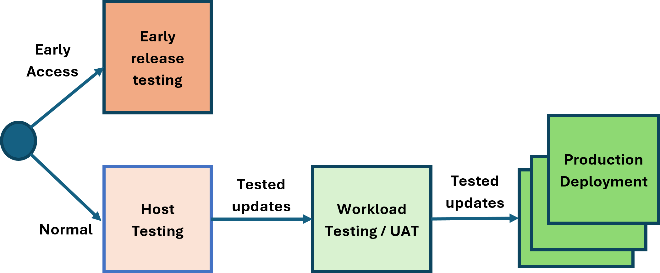
Optional:
The host testing and workload testing phases are optional. The reference architecture supports operating with or without these phases.
The host testing and workload testing stages do not have to be separate stages; they can be combined. This can be advantageous as it reduces the time to get through changes to production. The XenServer update stream is robust and fully tested, allowing continuous deployment. To maintain security, robustness, and performance, it is important to minimize the time updates take to reach production.
The expectations for each phase are as follows:
- Early Release Testing: This phase is intended for early visibility of updates and validation of features. Hosts in this phase are configured to use the early release channel, which typically provides access to new versions 2 weeks before the normal channel. Hosts in this phase must have outbound connectivity to the internet (either directly or via a proxy server) to access the XenServer Content Distribution Network (CDN).
- Host Testing: The purpose of this phase is to test the XenServer software release update processes. Releases are available over the internet from the XenServer CDN or through the offline channel delivery mechanisms.
- Workload testing/UAT: This phase enables the XenServer hosts to be tested with a production-like workload to validate scale and resiliency. Releases are available over the internet from the XenServer CDN or through the offline channel delivery mechanisms.
- Production Deployments: The hosts running production workloads can be updated following the previous testing phases (directly or through the offline delivery mechanisms).
Note:
Offline updates can be used to ensure that the expected version of XenServer is deployed to the UAT and production environments. It is possible to synchronize updates directly from another resource pool, however, if there are updates synchronized but not yet applied to the source pool, they may be applied to the destination pool, resulting in a higher patch version on the destination pool.
To remain supported, all resource pools need to be updated regularly and not be outdated by more than 6 months.
Monitoring the resource pool
When alerts occur in the resource pool for any of the hosts or VMs, these are available in the Alerts section of XenCenter®.
These alerts can also be made available in an external monitoring tool via SNMP integration or through email SMTP integration.
There are 2 types of monitoring to be considered.
- Monitoring for utilization, to ensure that any unexpected capacity issues are identified quickly and can be acted on.
- Monitoring for system events to ensure that infrastructure is operating correctly and that there are no unexpected changes occurring.
These are detailed below to be considered in the design for integration.
Integration to 3rd-party monitoring products can be made through the SNMP feature described here and can provide alerts that are integrated into those 3rd-party tools.
Note:
When adding a new host to the pool you must reconfigure the SNMP settings to ensure that the new host is included in any SNMP integration (see constraints for details).
Monitoring for usage
There are alerts that can be configured for detecting things like excessive CPU usage, see Performance Alerts for details.
Below is an example of the data provided in the SNMP traps fired for these events.
2026-02-19 09:44:35 <UNKNOWN> [UDP: [10.71.64.14]:53876->[10.81.143.35]:162]:
iso.3.6.1.2.1.1.3.0 = Timeticks: (196826250) 22 days, 18:44:22.50       iso.3.6.1.6.3.1.1.4.1.0 = OID: iso.3.6.1.4.1.60953.1.10.1   iso.3.6.1.4.1.60953.1.10.1.1.0 = STRING: "add"  iso.3.6.1.4.1.60953.1.10.1.2.0 = STRING: "OpaqueRef:eea63153-f96c-25f5-17b9-08ce49e7ccf4"   iso.3.6.1.4.1.60953.1.10.1.3.0 = STRING: "83a9c805-a172-f1b2-55d4-081ec180893b" iso.3.6.1.4.1.60953.1.10.1.4.0 = STRING: "ALARM"    iso.3.6.1.4.1.60953.1.10.1.5.0 = INTEGER: 3     iso.3.6.1.4.1.60953.1.10.1.6.0 = STRING: "VM"       iso.3.6.1.4.1.60953.1.10.1.7.0 = STRING: "681e4064-16cb-4d0c-9c2c-887623bc623f" iso.3.6.1.4.1.60953.1.10.1.8.0 = STRING: "20260219T09:45:55Z"       iso.3.6.1.4.1.60953.1.10.1.9.0 = STRING: "The memory required by the control domain on \"Control domain on host: pm-demolab-3\" is about 5.7% of its allocated memory. Occasional performance degradation can be expected when memory swapping is forced to happen.
This alarm is set to be triggered when the memory required by the control domain is above 5.0% of its allocated memory."
<!--NeedCopy-->
Monitoring for system events
The system alerts are described here
Below is an example of the data provided in the SNMP traps fired for these events.
2026-02-19 09:43:39 <UNKNOWN> [UDP: [10.71.64.14]:46982->[10.81.143.35]:162]:
iso.3.6.1.2.1.1.3.0 = Timeticks: (196820650) 22 days, 18:43:26.50       iso.3.6.1.6.3.1.1.4.1.0 = OID: iso.3.6.1.4.1.60953.1.10.1   iso.3.6.1.4.1.60953.1.10.1.1.0 = STRING: "add"  iso.3.6.1.4.1.60953.1.10.1.2.0 = STRING: "OpaqueRef:ca95e2da-06b7-9aa5-fa4b-ddf007a50c59"   iso.3.6.1.4.1.60953.1.10.1.3.0 = STRING: "525e459c-51bc-c71c-9c52-dcd747e9a84f" iso.3.6.1.4.1.60953.1.10.1.4.0 = STRING: "ALL_RUNNING_VMS_IN_ANTI_AFFINITY_GRP_ON_SINGLE_HOST"      iso.3.6.1.4.1.60953.1.10.1.5.0 = INTEGER: 3iso.3.6.1.4.1.60953.1.10.1.6.0 = STRING: "Pool"  iso.3.6.1.4.1.60953.1.10.1.7.0 = STRING: "419d6735-5d11-56b1-8cdc-2853ce709a27"     iso.3.6.1.4.1.60953.1.10.1.8.0 = STRING: "20260219T09:44:59Z"   iso.3.6.1.4.1.60953.1.10.1.9.0 = STRING: "<body><message>Breach on VM anti-affinity rules</message><VM_group>3224f9d9-9492-06f7-3c92-da610cde33a8</VM_group><host>ce2a3c26-6bbc-4d23-8626-fba28d3dc651</host></body>"
<!--NeedCopy-->
Remote Logging
The primary purpose of this is to enable support engagement. To ensure the availability of this data during issue resolution, syslog forwarding can be configured. This enables the logs to be retrieved in the event they cannot be retrieved from the host directly, or if there is any reason to suspect logs on the host may have been tampered with.
If this is configured, then this must be configured on all hosts in the pool.
This data can consume significant space. Use and retention of this feature and the data is at your discretion based on internal security policies.
Capacity Planning Model
Sizing the Resource Pool
Each resource pool should contain enough resources so that if 1 host is down the resource pool can operate the full workload. This will enable:
- Planned outage to occur as needed on 1 host at a time
- Resource pool updates to be made without any outage of workload
- Ensure minimal workload outage if 1 host unexpectedly fails
To achieve this the expectation is that all hosts in the resource pool have the same ability to support workload (i.e. same configuration, RAM, CPU). This may result in a higher level of CPU overcommit during outage, but this is expected to be short lived until the outage condition is resolved.
If more than 1 host in a resource pool is lost it will no longer be possible to maintain all workload and there may be a workload outage until hosts are recovered.
Note:
If hosts do not have identical capacity for periods of time during activities like hardware update/refresh, allowance should be made for the failure of the host with the most memory
Resource Pool Capacity calculations
In this reference architecture, we have assumed each resource pool is for a specific purpose. As a result, the calculations below assume that all VMs in the resource pool are the same specification.
Dom0 is sized to 32 GB RAM. However, if PVS accelerator is being used this will need to be increased by at least 5 GB per vdisk to support the acceleration and must be taken into account in these calculations.
Inputs
| Term | Definition |
|---|---|
host_ram |
Total RAM in each Host (in GB) |
vm_ram |
RAM requirement for each VM (in GB) |
host_cpus |
Number of vCPUs available in the host (these are logical CPUs so include threads) |
vm_cpus |
vCPUs required for each VM |
hosts_total |
Number hosts in pool |
vm_disks |
Number of disks attached to each VM |
vm_snapshots |
Expected number of snapshots per VM |
dom0_ram |
Memory reserved for Dom0 (32 GB for this reference architecture) |
dom0_vcpus |
vCPUs reserved for Dom0 (16 for this reference architecture) |
wlb_ram |
Memory required for WLB appliance (2GB for this reference architecture) |
wlb_vcpus |
vCPUs required for WLB appliance (2 for this reference architecture) |
Outputs
| Term | Definition | Formula |
|---|---|---|
vm_host_max |
Maximum number VMs running on each host in the pool | (host_ram - dom0_ram - wlb_ram) / vm_ram |
vm_pool_max |
Maximum number of VMs that could run in the pool | vm_host_max * (hosts_total - 1) |
srs_total |
Number of Storage Repositories needed to host the VMs | vm_pool_max * (vm_disks + vm_snapshots) / 1000 |
vm_host |
Number of VMs actually running on the host |
vm_pool_max / hosts_total (see note) |
host_cpu_overcommit |
Number of vCPUs required in the host to run the required workload (these are logical CPUs so include threads) | ((vm_host * vm_cpus) + dom0_vcpus + wlb_vcpus) / host_cpus |
Note:
During host failure, maintenance, or update operation
vm_host = vm_pool_max / (hosts_total - 1)
Worked Example
| Term | Value |
|---|---|
host_ram |
1000 GB (1 TB) |
vm_ram |
16 GB |
host_cpus |
2 sockets each with 32 threaded cores = 2 * 32 * 2 = 128 |
vm_cpus |
4 |
hosts_total |
8 |
vm_disks |
MCS VMs = 1 ID disk, 1 OS disk, 1 MCSIO disk = 3 |
vm_snapshots |
0 |
dom0_ram |
32 |
dom0_vcpus |
16 |
wlb_ram |
2 |
wlb_vcpus |
2 |
vm_host_max = (1000 - 32 - 2) / 16 = 60 max VMs per Hostvm_pool_max = 60 * (8 - 1) = 420 max VMs per poolsrs_total = 420 * (3 + 0) / 1000 = 1.26 SRs (>1 so need 2 SRs spread over 2 LUNS)-
Normal operation:
vm_host = 420 / 8 = 52.5 VMs per host (round down to 52)host_cpu_overcommit = ((52 * 4) + 16 + 2) / 128 = 1.77 vCPU per pCPU
-
During single host outage or update/maintenance operation:
vm_host = 420 / 7 = 60 VMs per hosthost_cpu_overcommit = ((60 * 4) + 16 + 2) / 128 = 2.01 vCPU per pCPU
Note:
There is no usage of Dynamic Memory Control (DMC) to provide RAM overcommit. XenServer does not support this during normal operation. This is only expected to be used during short periods of planned controlled maintenance when no other option is available to keep required workload running.
If the overcommit is too high, then the number of VMs for the pool will need to be reduced until it reaches an acceptable point.